Modal
YES, YES, YES: GENEIS92, my apologies to both of you. I'm old and easily confused - LOL
In any case, glad there are still folks staying on top of this module
XV-5080 encoder replacement
-
bluesplayer
- Posts: 136
- Joined: 00:40, 4 October 2004
- Location: Rio Rancho NM

Re: XV-5080 encoder replacement
ok Modal, I will make a new post soon about the encoder replacement ;)
Re: XV-5080 encoder replacement
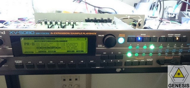
as requested here are the details on how to replace the XV-5080 encoder.
-> you make it at your own risks and you must have electronic skills to do it.
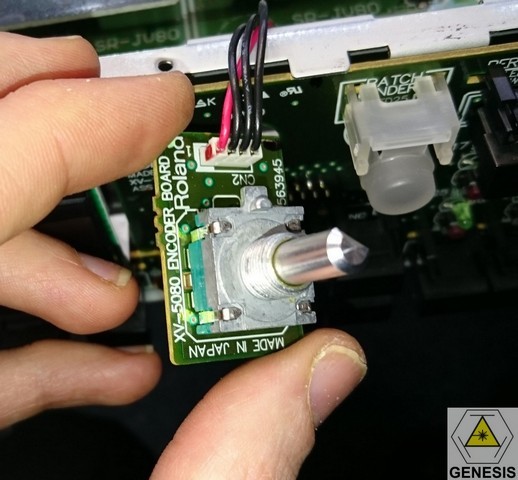
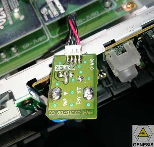
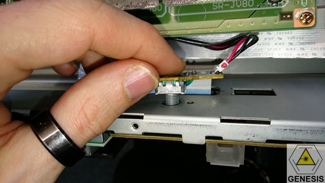
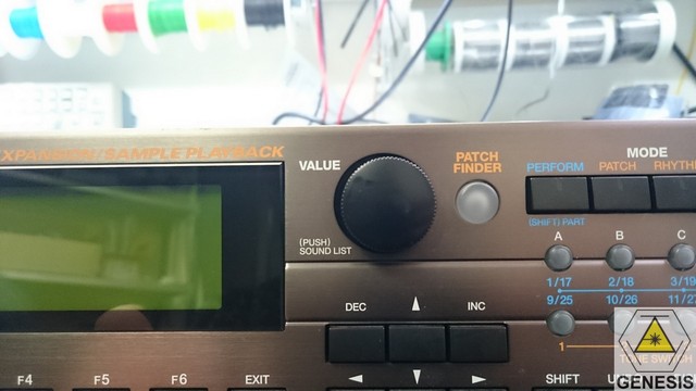
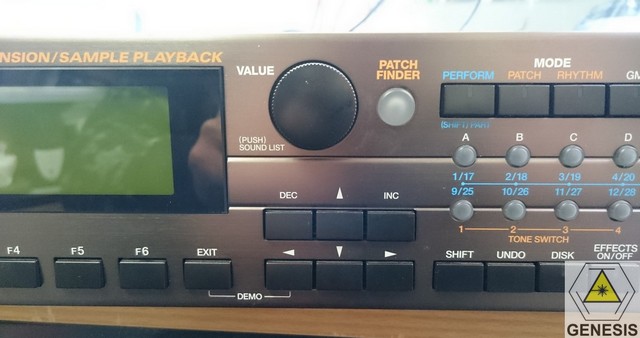
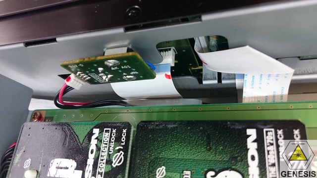
To get the old encoder you must open the cover and remove carefully the front panel.
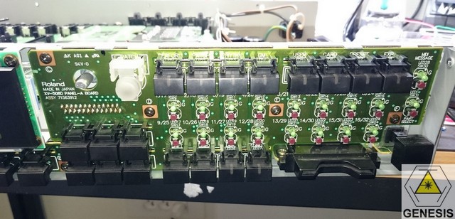
Remove the crews holding the right switch panel PCB
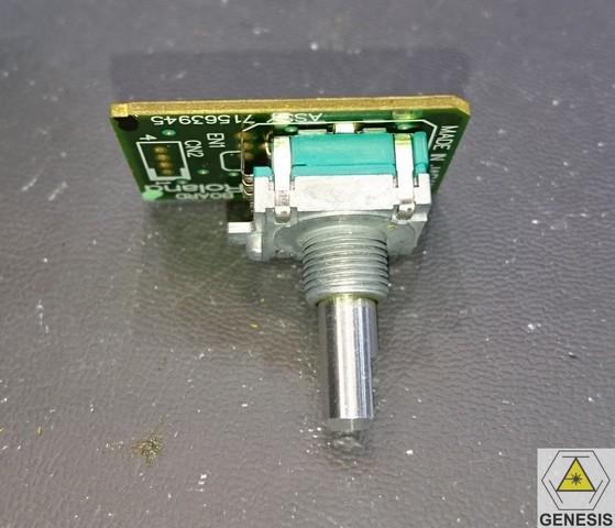
The original part from ALPS
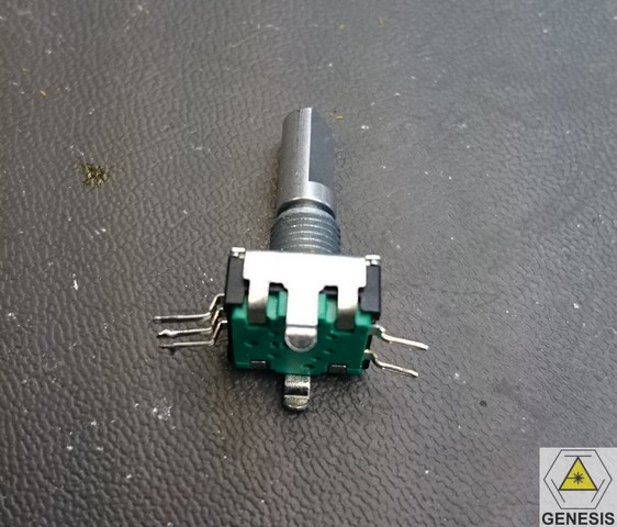
the specs of the new one.
it seems electrically compatible but with a thinner threaded shaft.
the number of detents is lower than the original (24 instead of 36 but it's not an issue)
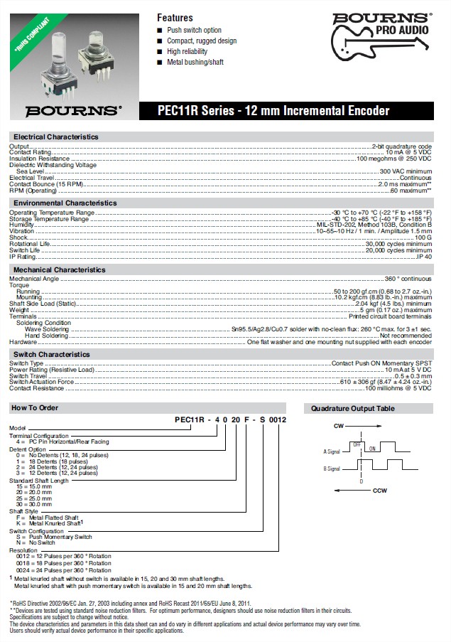
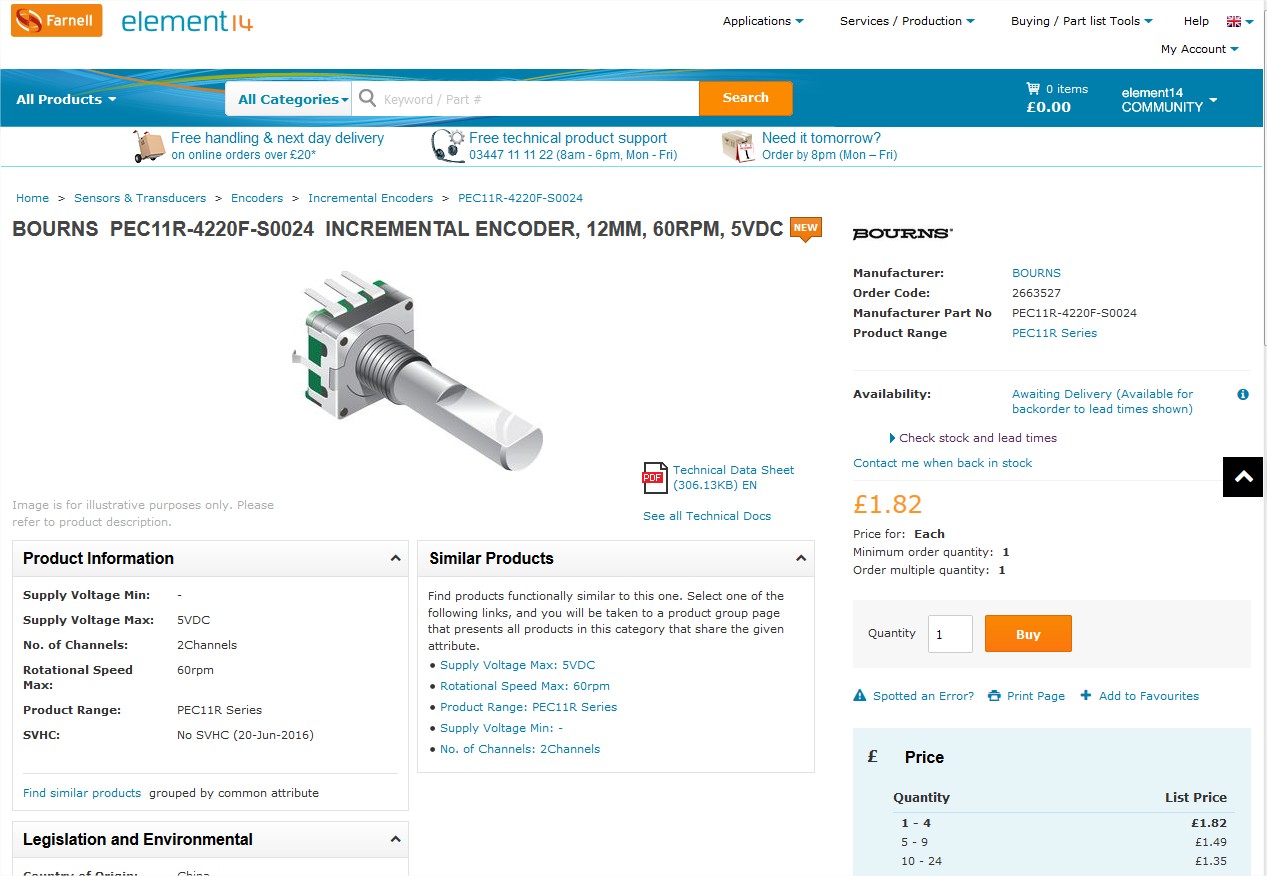
here is its part number: PEC11R-4220F-S0024
we can order it from Farnell, RS, Digikey and mouser.
it's not an expensive part
a first test to confirm it works but the service manual schematics shows a
quadrature decoder instead of the JD-990. so all works fine
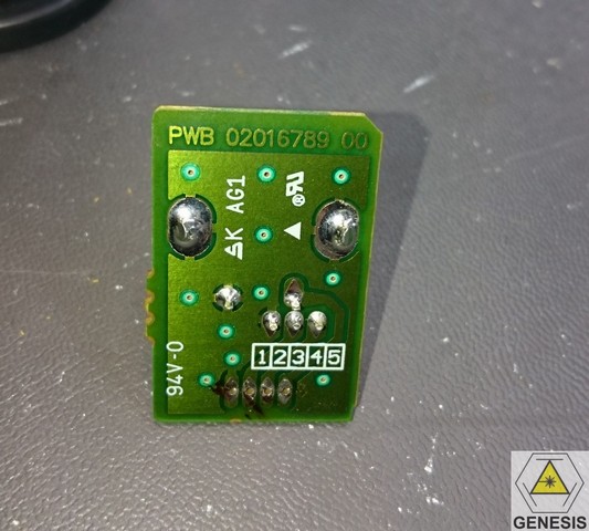
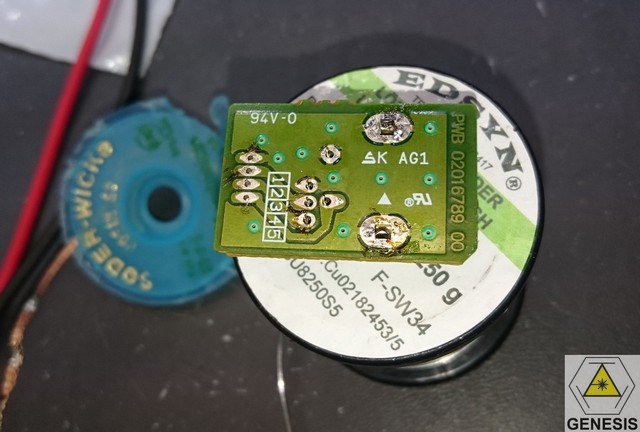
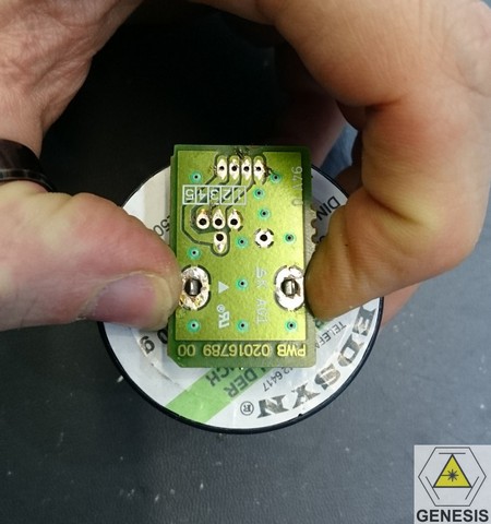
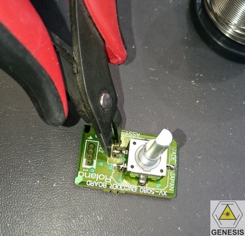
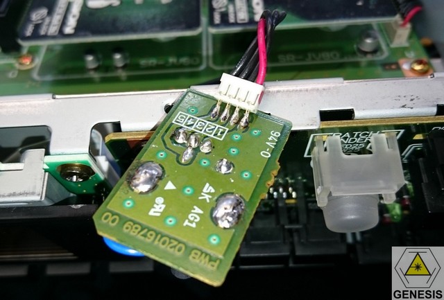
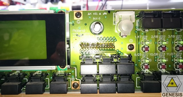
first step is to detach the PCB from the cable with solder iron and solder wick.
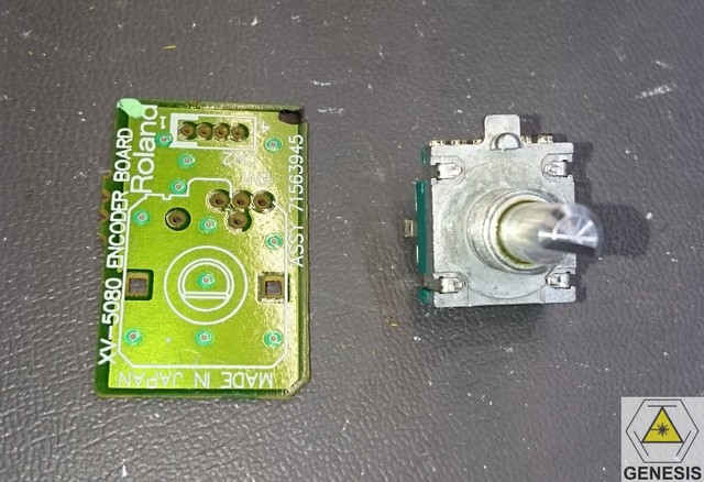
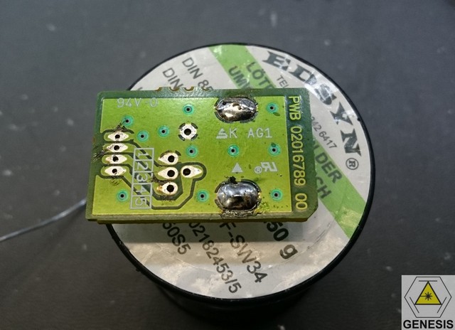
use solder wick to remove the old encoder
the old encoder uses a strange pinout so we must modify the wiring to the new one
bend the pins
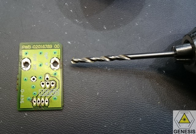
drill two larger holes with 3mm bit
cut the two external pins
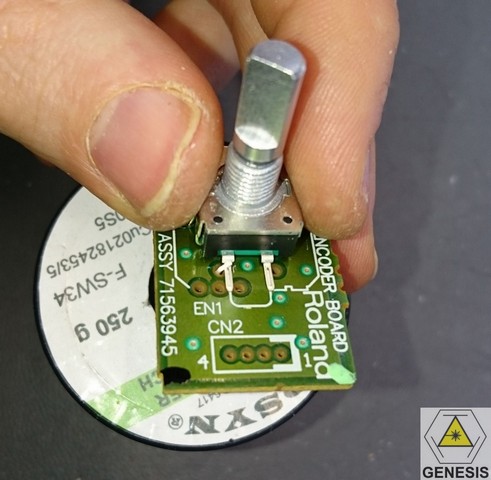
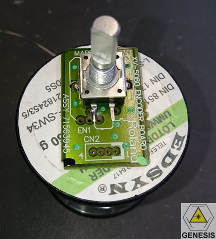
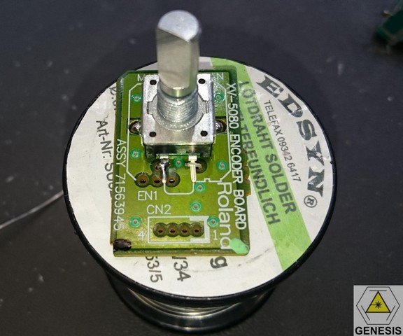
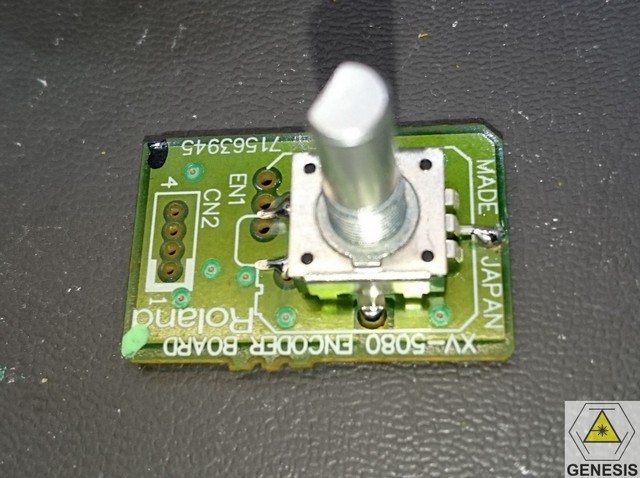
put the new encoder on the PCB
and solder it in place
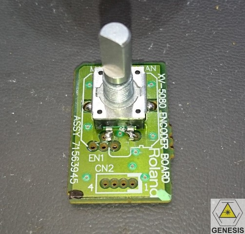
use a bit of tinned copper wire and make a right angle as a hoock
solder it to the encoder pin
and on the bottom of the PCB
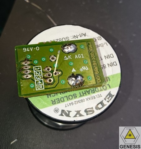
do the same thing for the other pin
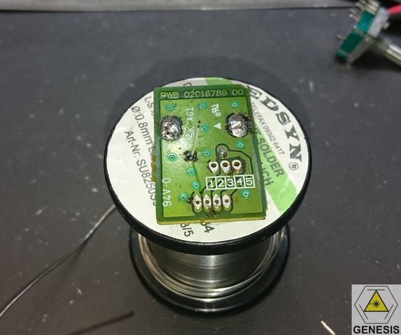
and cut the copper wire
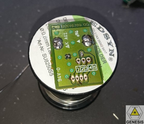
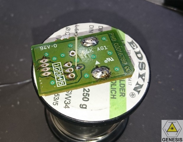
remove the green varnish of the PCB near the center pad of the encoder
to get a ground contact
solder the pin to this ground connection
cut what exceeds
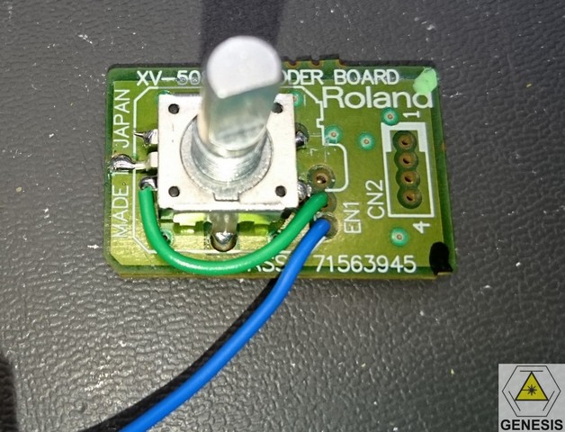
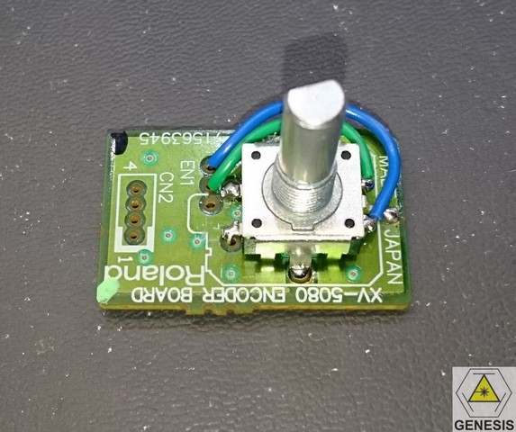
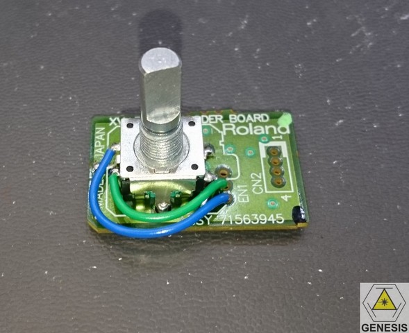
now use two insulated wires to make the A and B connections to the encoder and solder them like on the pictures
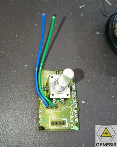
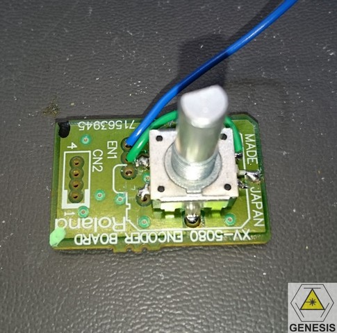
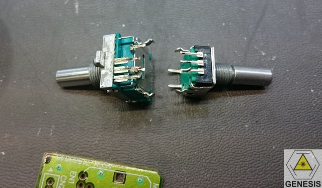
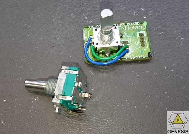
the new and old encoders side by side
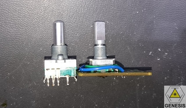
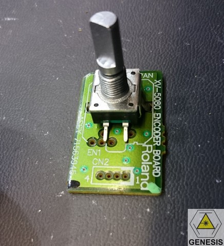
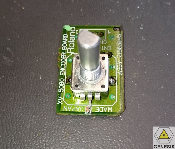
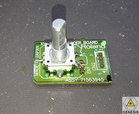
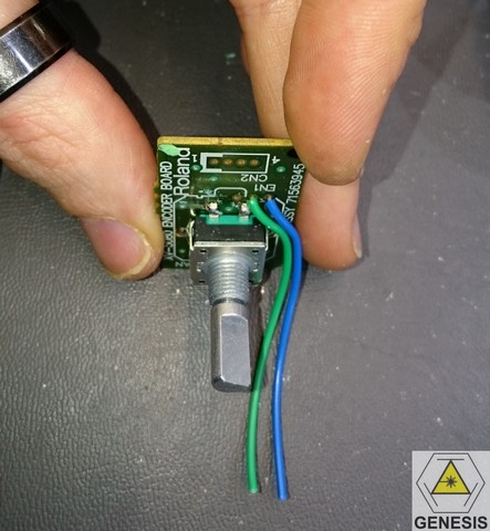
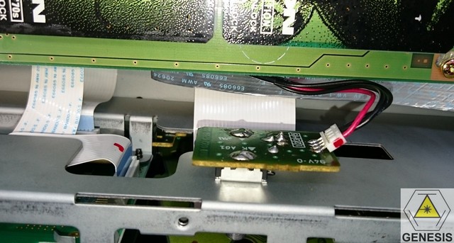
the PCB ready to be installed back in the unit
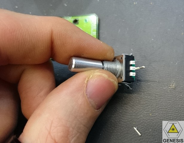
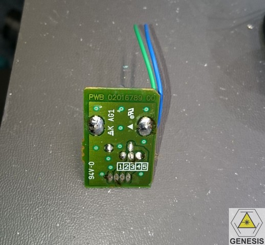
the new encoder is thinner than the old one and thus we must solder
the cable on the bottom of the PCB like on the picture
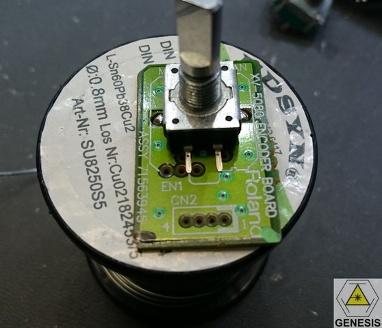
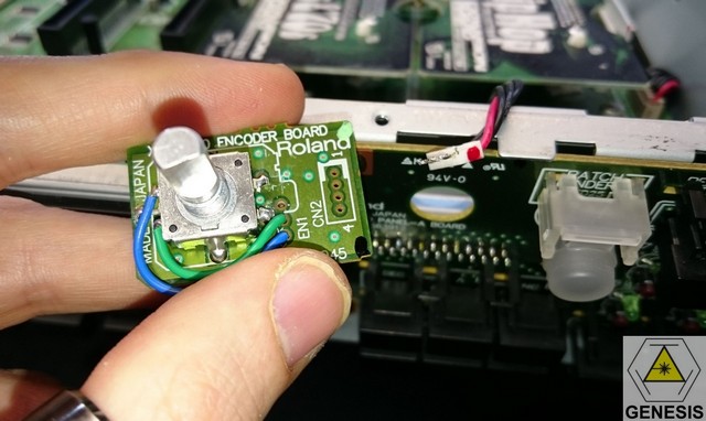
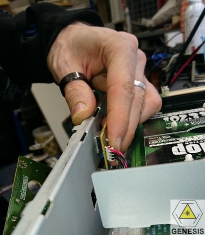
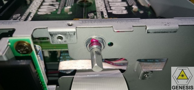
put the encoder back on the front
put the washer
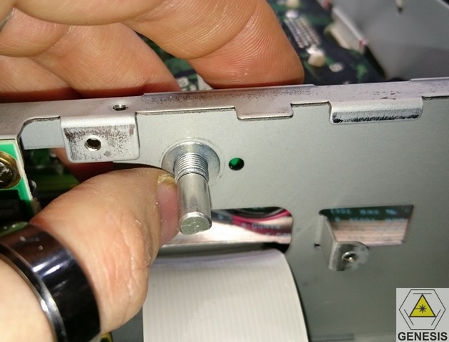
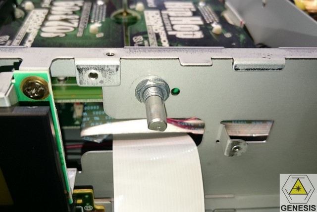
check the alignment
use the hole to set the middle position
and tight gently the bolt
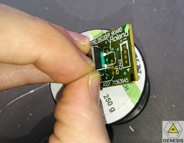
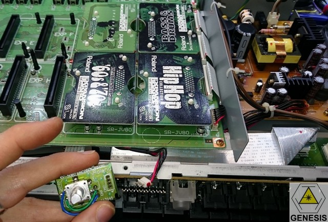
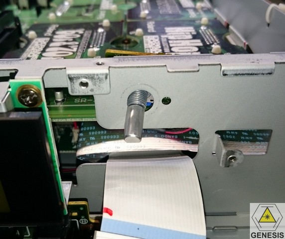
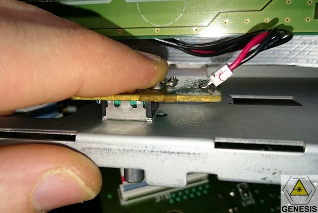
you can now check with the switches front panel PCB hole if the encoder
is right in place
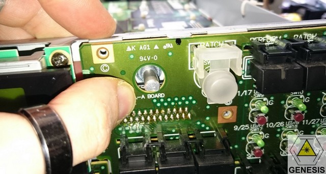
check if it fit in the middle of the front panel
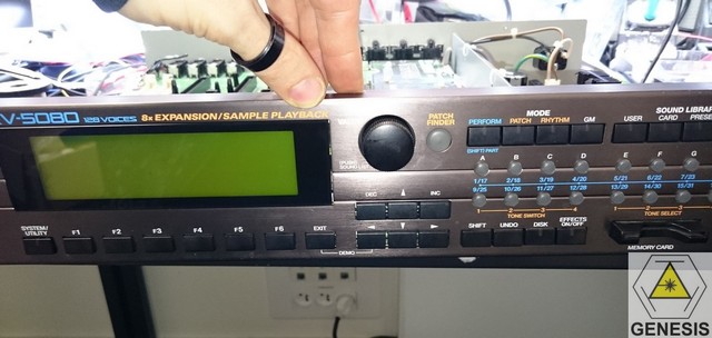
and if it works well
the first time it was not in the middle so....
you must align it again and when it's ok you can tight the bolt
use locking (or standard) varnish to be sure
and voila! a new working encoder for your XV-5080! enjoy!
-> you make it at your own risks and you must have electronic skills to do it.
To get the old encoder you must open the cover and remove carefully the front panel.
Remove the crews holding the right switch panel PCB
The original part from ALPS
the specs of the new one.
it seems electrically compatible but with a thinner threaded shaft.
the number of detents is lower than the original (24 instead of 36 but it's not an issue)
here is its part number: PEC11R-4220F-S0024
we can order it from Farnell, RS, Digikey and mouser.
it's not an expensive part
a first test to confirm it works but the service manual schematics shows a
quadrature decoder instead of the JD-990. so all works fine
first step is to detach the PCB from the cable with solder iron and solder wick.
use solder wick to remove the old encoder
the old encoder uses a strange pinout so we must modify the wiring to the new one
bend the pins
drill two larger holes with 3mm bit
cut the two external pins
put the new encoder on the PCB
and solder it in place
use a bit of tinned copper wire and make a right angle as a hoock
solder it to the encoder pin
and on the bottom of the PCB
do the same thing for the other pin
and cut the copper wire
remove the green varnish of the PCB near the center pad of the encoder
to get a ground contact
solder the pin to this ground connection
cut what exceeds
now use two insulated wires to make the A and B connections to the encoder and solder them like on the pictures
the new and old encoders side by side
the PCB ready to be installed back in the unit
the new encoder is thinner than the old one and thus we must solder
the cable on the bottom of the PCB like on the picture
put the encoder back on the front
put the washer
check the alignment
use the hole to set the middle position
and tight gently the bolt
you can now check with the switches front panel PCB hole if the encoder
is right in place
check if it fit in the middle of the front panel
and if it works well
the first time it was not in the middle so....
you must align it again and when it's ok you can tight the bolt
use locking (or standard) varnish to be sure
and voila! a new working encoder for your XV-5080! enjoy!
-
bluesplayer
- Posts: 136
- Joined: 00:40, 4 October 2004
- Location: Rio Rancho NM
Re: XV-5080 encoder replacement
Thanks from this forumite
Great detailed "how to." I use to be a electronics tech in another life [TUBE age avionics] and still do own amp and other repairs/mods so not adverse to this kind of work - just too lazy to do the needed homework.
Again thanks
Great detailed "how to." I use to be a electronics tech in another life [TUBE age avionics] and still do own amp and other repairs/mods so not adverse to this kind of work - just too lazy to do the needed homework.
Again thanks
Re: XV-5080 encoder replacement
you're welcome ;)